Chapter 9: Standard welding symbol
Introduction
Blueprints or drawing of final products are provided to worker or welders before the welding jobs starts. Welder studies the blueprints and plans according to it. There are standard symbols used in welding industry to make the similar understanding about any task. The main elements of welding symbols are:
Reference line
Arrow
Basic weld symbol
Dimension and other data
Finish symbol
Tail
Supplementary symbol
Specification, process or other symbol
Standard location of welding symbol element
- Welding symbols have their standard location to ease welder from complexity of design. The figure with symbol on standard location is shown below. From the given figure we can get following information:
Type of joint
Position of joint
No of weld
Method of welding
Edge preparation
Requirement of full or partial welding
Size and depth of the bead
Length of the weld
Further direction and so on.

Basic welding symbol
Location Significance |
Arrow side |
Other side |
Both side |
|---|---|---|---|
Fillet |

|
|

|
Plug or Slot |
|

|
Not used |
Spot or Projection |
|
|
Not used |
Stud |
|
Not used |
Not used |
Back |

|
|
Not used |
Surfacing |
|
Not used |
Not used |
Edge |
|

|
|
Seam |
|

|
Not used |
Symbols for different groove according to location signification is given below:
Location Significance |
Arrow side |
Other side |
Both side |
|---|---|---|---|
Square |

|

|

|
V |

|

|

|
Bevel |

|

|

|
U |

|

|

|
J |

|

|

|
Flare - V |

|

|

|
Flare - Bevel |

|

|

|
Scarf for Brazed joint |

|

|

|
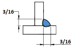
Example of a welding symbol for a fillet weld
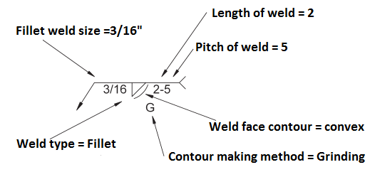
The given information is shown in the drawing below:
Supplementary symbol
S/n |
Description |
Other side |
|---|---|---|
Weld all around |

|
|
Field weld |

|
|
Melt through |

|
|
Concave contour |

|
|
Convex contour |

|
|
Flush contour |

|
|
Backing (rectangle) |

|
|
Spacer (rectangle) |

|
|
Consumable inert (square) |

|
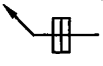
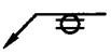
Some of the implementations are shown below:


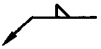
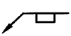
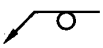
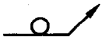
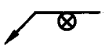
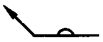
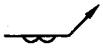
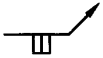
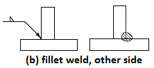
Importance of position of arrow
While preparing the drawing or blueprint of welding with standard symbols, an arrow should touch the location where welding is required. A location touched by arrow is known as arrow side. A position of arrow as symbol in left side and its implementation in right side is shown in figures below:


What’s next?
This will be the end of our journery. To dive deep in the welding field there are lots of resouces available…